


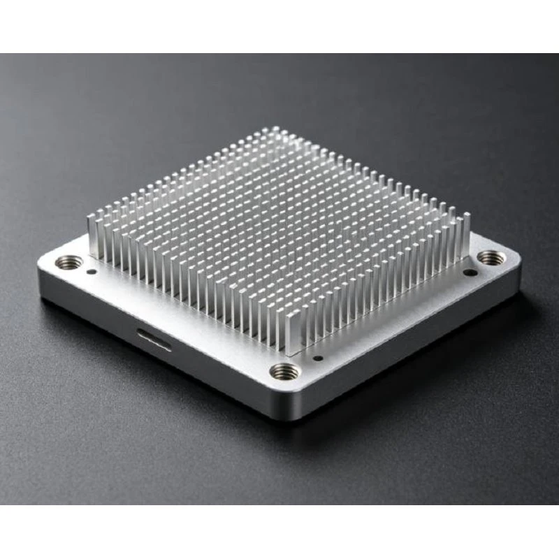
High-Density Fin Heat Sinks
High-density fin heat sinks are CNC-machined aluminum thermal components with closely spaced fins for increased heat-dissipation area within a controlled footprint. The fin array, base, mounting holes, threads, counterbores, and locating features can be machined as one component.
The design is defined by the heat-source footprint, available installation space, airflow path, fin geometry, material, and mounting interface. Production can follow a 2D drawing, 3D CAD model, approved sample, or defined specification, with critical dimensions controlled against the approved part definition.
High-Density Fin Structure
Fin Pitch
Fin pitch defines the distance between adjacent fins and determines how many fins can fit within the available width. A typical reference range is 1.5–4.0 mm. The final pitch should account for airflow, fin height, heat load, and machining requirements.
Fin Thickness
Typical machined fin thickness ranges from 0.8–2.0 mm. The selected thickness depends on fin height, pitch, material, machining depth, and required mechanical rigidity.
Fin Height
A typical reference range is 10–50 mm. Height is selected according to enclosure clearance, airflow direction, thermal surface area, and the position of the heat source.
Material Options
Aluminum Alloys
Aluminum 6061 and 6063 are commonly specified for CNC-machined heat sinks. Material selection considers thermal performance, weight, machinability, mechanical requirements, and the required surface treatment.
Material Control
The drawing should identify the alloy, temper, and material condition. Material identification can be maintained through the production record when material documentation is required.
Key Specifications
|
Parameter |
Typical Reference |
|
Material |
Aluminum 6061 / 6063 |
|
Fin Thickness |
0.8–2.0 mm |
|
Fin Pitch |
1.5–4.0 mm |
|
Fin Height |
10–50 mm |
|
Base Thickness |
3–10 mm |
|
Overall Length |
Up to 300 mm* |
|
Overall Width |
Up to 200 mm* |
|
Contact Surface Flatness |
0.05–0.15 mm* |
|
Mounting Hole Diameter |
2–12 mm* |
|
Surface Roughness |
Ra 1.6–3.2 μm* |
|
Surface Treatment |
Anodizing or specified finish |
Reference values for preliminary specification review. Final dimensions and tolerances follow the approved drawing and application requirements.
CNC Machining Process
Material Preparation
Aluminum stock is selected according to the specified alloy, temper, and starting dimensions. Machining allowance is established before producing the final fin and base geometry.
Fin Machining
CNC milling forms the fin array and controls fin pitch, thickness, height, and base connection. The machining sequence is selected according to fin geometry and the number of required machining faces.
Secondary Operations
Drilling, tapping, counterboring, chamfering, pocketing, and deburring complete the mounting and interface features. Hole locations and thread specifications follow the approved drawing.
Surface Treatment
Anodizing or another specified finish can be applied after machining. Thermal contact areas, threads, and other functional surfaces can be identified for treatment or masking requirements.
How to Select the Right Heat Sink
Match the Fin Density
Begin with the available footprint and airflow direction. A smaller pitch increases the number of fins in a given area, while the selected channel spacing must remain appropriate for the intended airflow path.
Check the Base Geometry
The base provides the thermal interface and mounting structure. A reference base thickness of 3–10 mm covers many compact machined configurations, while the final thickness depends on mechanical loading and heat-transfer requirements.
Confirm Installation Space
Check length, width, total height, mounting-hole position, connector clearance, and fin clearance against the equipment envelope before releasing the heat sink design.
Define the Thermal Interface
The heat-source contact surface may require controlled flatness and surface finish. A reference flatness range of 0.05–0.15 mm can be used during preliminary specification review; the final value should be stated on the drawing.
Typical Applications
Power Electronics
Used for compact power modules, converters, drivers, and electronic assemblies where heat must move from a defined mounting surface to an exposed fin structure.
Industrial Controls
Suitable for control units, drive components, embedded electronics, and compact electrical assemblies with localized heat sources.
Communication Equipment
High-density fin configurations can be incorporated into compact equipment where thermal surface area, enclosure height, and airflow clearance must be considered together.
Lighting and Electronic Assemblies
Used for LED modules, electronic drivers, and other heat-generating assemblies requiring a machined aluminum thermal interface.
Quality and Inspection
Dimensional Inspection
Inspection focuses on fin thickness, fin pitch, fin height, base thickness, overall dimensions, mounting-hole locations, and the thermal contact surface.
Surface Inspection
Machined surfaces are checked for burrs, edge condition, and surface quality. The thermal contact area is evaluated against the specified flatness and surface-finish requirements.
Critical Feature Control
Fin geometry and mounting interfaces are checked against the approved drawing and defined inspection criteria. Measurement records can be retained for specified critical characteristics.
Information Required for Quotation
Technical Documents
Provide a 2D drawing or 3D CAD model showing overall dimensions, fin geometry, mounting features, material, tolerances, and surface treatment requirements.
Thermal Requirements
Include heat load, heat-source footprint, airflow direction, available installation space, and thermal interface requirements when these parameters are available.
Quantity and Finish
State the required quantity, prototype or production status, material specification, surface treatment, inspection requirements, packaging requirements, and documentation requirements.
FAQ
Q: What material is commonly specified for high-density fin heat sinks?
A: Aluminum 6061 and 6063 are common choices for CNC-machined heat sinks. The final alloy should match the thermal, mechanical, machining, and surface-treatment requirements of the part.
Q: What fin pitch should be selected?
A: A 1.5–4.0 mm reference range covers many compact machined configurations. The final pitch depends on fin height, airflow, heat load, available space, and the required machining geometry.
Q: Can mounting holes and threads be integrated?
A: Yes. Through holes, tapped holes, counterbores, pockets, and locating features can be machined directly into the heat sink according to the assembly drawing.
Q: Can the thermal contact surface have a specified flatness?
A: Yes. Flatness and surface finish can be defined for the heat-source contact area. The required values should be stated on the drawing according to the thermal interface and assembly design.
Hot Tags: high-density fin heat sinks, China high-density fin heat sinks manufacturers, suppliers, factory, 5 axis cnc, cnc lathing, CNC Plasma Parts, cnc production machining, high precision machining, precision cnc turning
Previous
Aluminum Pin-Fin Heat SinksYou Might Also Like


Send Inquiry