


CNC Machined Robotic Joint Components
Custom CNC Machined Robotic Joint Components Manufacturer
Custom CNC manufacturing for robotic joint housings, actuator components, bearing interfaces, flanges, adapters, and structural parts. Components are produced from approved drawings, CAD models, samples, or defined specifications, with machining, surface treatment, inspection, and packaging coordinated around the required assembly conditions.



Why Choose Us
Aluminum-Focused Production
Aluminum machining supports lightweight joint housings, actuator bodies, mounting structures, covers, and connection components. Material selection can be matched to strength, weight, machinability, and surface treatment requirements.
Multi-Axis Machining Capabilities
3-axis, 4-axis, and 5-axis CNC machining supports multi-face components, angled features, deep pockets, and complex joint structures. Machining strategies are selected according to part geometry, tolerance requirements, and production quantity.


Integrated Manufacturing Workflow
CNC machining can be coordinated with tooling, die casting, secondary machining, deburring, and surface treatment. This allows related processes to follow the same drawing revision and production requirements.
Certified Quality and Engineering Support
Engineering review covers material, dimensions, tolerances, machining features, and surface requirements before production. Inspection records and production controls support consistent part verification throughout the manufacturing process.
Robotic Joint Components We Manufacture
Joint Housings
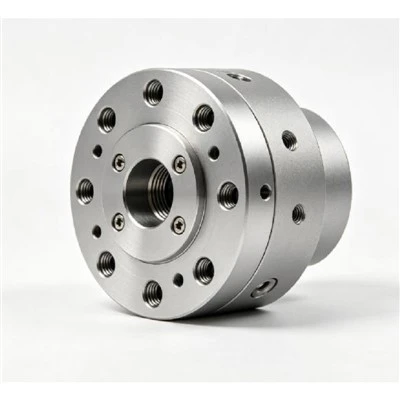
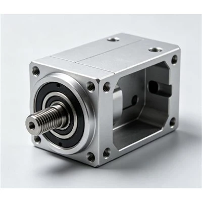
Machined housings accommodate bearings, motors, reducers, fasteners, and internal components. Bearing bores, mounting faces, cover interfaces, and locating features are controlled according to the approved drawing.
Actuator Components
Actuator bodies, motor plates, end covers, brackets, and connecting parts can be machined for compact motion assemblies. Critical mounting locations are referenced from defined datums during machining and inspection.
Bearing Interfaces
Bearing seats, locating bores, shoulders, and mating surfaces are machined according to specified diameter, depth, concentricity, and positional requirements.
Flanges and Joint Adapters
Output flanges, adapter plates, reducer interfaces, and mechanical connectors provide defined mounting patterns between related motion components. Hole spacing, locating diameters, and interface thickness are controlled from the drawing.
Precision Features for Robotic Joints
Bearing Bores and Seats
Bearing locations can be machined with controlled bore dimensions, shoulder depths, and locating surfaces to support the specified bearing fit and assembly alignment.
Motor Mounting Surfaces
Flat mounting datums and controlled bolt-hole patterns provide defined interfaces for motor installation. Surface condition and hole position are checked according to drawing requirements.
Reducer and Drive Interfaces
Reducer mounting faces, locating bores, bolt circles, and coaxial features are machined from established datums to maintain the required relationship between connected components.
Output Flanges and Locating Features
Output interfaces can include locating pilots, bolt patterns, dowel holes, and flange faces for repeatable mechanical assembly and load transfer.
Threaded Holes and Counterbores
Tapped holes, counterbores, countersinks, and clearance holes are machined to the specified thread size, depth, diameter, and positional tolerance.
Internal Pockets and Cavities
Internal pockets and cavities can reduce unnecessary material while providing space for cables, fasteners, bearings, and other internal components. Wall thickness and remaining structural sections are reviewed during process planning.
Datum Reference Surfaces
Primary and secondary datums establish machining and inspection references. Datum selection helps maintain the dimensional relationship between bores, mounting faces, holes, and other functional features.
Materials
Material selection is based on mechanical requirements, part geometry, machining conditions, surface treatment, and intended application.
|
Item |
Available Options / Reference |
|
Aluminum Alloys |
6061, 6063, 6082, 7075 |
|
Other Metals |
Brass, stainless steel, and selected engineering metals |
|
CNC Processes |
Milling, turning, drilling, tapping, reaming, 3-axis, 4-axis, and 5-axis machining |
|
Surface Treatment |
Anodizing, hard anodizing, powder coating, electrophoresis |
|
Typical Dimensional Control |
According to approved drawing and feature requirements |
|
Quality System |
ISO 9001:2015 quality management system |
CNC Machining Capabilities
Complex Geometries
Multi-axis machining supports angled surfaces, curved profiles, deep pockets, intersecting features, and multi-face joint components. Setup and tool access are planned according to the actual geometry.
Critical Interfaces
Bearing seats, mounting faces, locating bores, bolt patterns, and functional datums receive process attention according to their assembly role. Machining sequences are arranged to maintain the required feature relationships.
Secondary Operations
Drilling, tapping, reaming, countersinking, deburring, chamfering, and related secondary operations can be incorporated into the production route. The selected process depends on material, feature size, tolerance, and surface requirements.
Applications
We offer a variety of transmission components
Industrial Robots
Joint housings, actuator structures, bearing interfaces, flanges, and mounting components support articulated industrial robot assemblies.
Collaborative Robots
Lightweight aluminum housings, motor mounts, joint covers, and compact structural components can be produced for space-sensitive robotic mechanisms.
Humanoid and Service Robotics
Compact joint structures, actuator housings, connection plates, and machined interfaces can be developed around limited installation space, weight requirements, and complex mechanical layouts.
Professional
Motion brackets, mounting plates, guide interfaces, housings, and structural connectors are suitable for automated assembly, positioning, handling, and inspection equipment.
Custom Manufacturing from Drawings
Flexible Input Formats
Production can be based on 2D engineering drawings, 3D CAD models, physical samples, or defined technical specifications. Required material, quantity, finish, tolerance, and inspection information can be reviewed before production.
Comprehensive Engineering Review
Pre-production review covers material selection, machining allowances, wall sections, hole structures, datum relationships, tolerance requirements, and surface treatment requirements.
Repeat Order Consistency
Approved drawing revisions, process records, inspection requirements, and production references are maintained for repeat orders. This provides a consistent basis for subsequent manufacturing runs.
First Article Inspection
Initial production parts are checked against applicable drawing dimensions, hole locations, interfaces, threads, surface requirements, and other specified characteristics before batch production proceeds.
Process Control
Critical dimensions and process conditions are monitored during production. Tool condition, machining sequence, feature location, and inspection results can be reviewed according to the part requirements.
Final Inspection
Finished components are inspected for dimensional conformity, thread condition, functional interfaces, surface condition, burrs, and visible machining defects before packing.

Surface Treatment

Standard Anodizing
Anodizing provides an oxide surface layer for aluminum components and can be specified according to required color, appearance, and corrosion-resistance conditions.
Hard Anodizing
Hard anodizing provides a harder aluminum surface for components exposed to repeated contact, sliding, or wear. Thickness and appearance requirements are confirmed according to the project specification.
Alternative Finishes
Powder coating and electrophoresis are available for projects requiring different appearance, protection, or environmental performance. Surface preparation and finish requirements are confirmed before processing.
Manufacturing Process
Drawing Review
Part dimensions, tolerances, material, surface requirements, and functional interfaces are reviewed before production.ctetur adipisicing elit.
Process Planning
Machining sequence, datum references, tool access, workholding, secondary operations, and inspection points are established according to the part structure.
Production and Finishing
CNC machining is followed by required drilling, tapping, deburring, surface treatment, and final inspection. Each stage follows the approved production requirements.
Prototype Samples
Prototype parts provide an initial check of dimensions, mounting relationships, bearing interfaces, surface treatment, and assembly fit before repeat production.
Sample Confirmation
Sample inspection focuses on the features that affect assembly and function. Approved changes are incorporated into the production drawing or process records before the next stage.
Batch Scalability
Validated processes can be transferred from prototype quantities to repeat production. Drawing revisions, inspection requirements, surface treatment specifications, and packaging methods remain aligned across production stages.

Packaging and Shipment
Component Protection
Bearing bores, threaded holes, machined faces, locating features, and finished surfaces are protected according to their handling requirements.
Separation Methods
Individual wrapping, foam separation, partitions, and protective materials can be used to prevent direct contact between finished components during transportation.
Custom Shipping Containers
Packaging can use corrugated cartons, protective foam inserts, pallets, or wooden crates according to component size, quantity, weight, and shipping requirements.

Technical Assistance
Engineering communication covers dimensional questions, assembly fit, drawing revisions, material selection, and surface treatment requirements after delivery.
Issue Resolution
Inspection information, dimensional records, photographs, and application feedback can be reviewed to identify the relevant manufacturing or assembly condition and determine the appropriate follow-up.
Engineering Collaboration
Ongoing support can cover drawing changes, new revisions, prototype updates, repeat production, surface treatment changes, and production scheduling.
FAQ
Q: Can robotic joint components be manufactured from custom drawings?
A: Yes. Production can be based on 2D engineering drawings, 3D CAD models, physical samples, or defined technical specifications. Material, quantity, tolerance, finish, and inspection requirements should be included where applicable.
Q: What aluminum alloy grades are available?
A: Common aluminum options include 6061, 6063, 6082, and 7075. The suitable grade depends on the required strength, weight, machinability, surface treatment, and application conditions.
Q: Can bearing bores and mounting interfaces be CNC machined?
A: Yes. Bearing bores, seats, mounting faces, locating diameters, bolt patterns, threaded holes, and other functional interfaces can be machined according to the specified dimensions and tolerances.
Q: Is 5-axis CNC machining available for robotic joint components?
A: 5-axis CNC machining can be used for components with multiple angled surfaces, complex contours, deep features, and several functional faces. The machining method is selected according to the part geometry and tolerance requirements.
Q: What information is needed for a quotation?
A: Provide the 2D drawing or 3D CAD file, material grade, required quantity, surface treatment, dimensional tolerances, inspection requirements, and packaging requirements. Assembly information is also useful when the component has critical mating interfaces.

Request a Quote for Custom Robotic Joint Components
Send your 2D drawing, 3D CAD file, material requirements, quantity, surface treatment, and inspection specifications. Our engineering team can review the component requirements and prepare a quotation based on your production needs.