


Robotic Arm Links
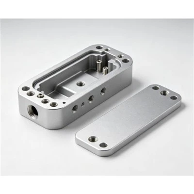
Robotic Arm Links are precision CNC machined structural components designed to connect motion sections and maintain accurate positioning between robotic joints.
Manufactured from aluminum alloys and engineering metals, these components are produced according to technical drawings, 3D CAD models, or supplied samples. CNC machining creates critical features including pivot holes, bearing interfaces, mounting surfaces, locating points, threaded holes, and weight-reduction pockets.
Robotic arm link performance depends on material selection, structural design, machining accuracy, and controlled manufacturing processes to achieve reliable assembly and consistent motion performance.
CNC Machining Capabilities for Robotic Arm Links
Precision Feature Machining
Robotic arm links require accurate machining of connection areas that directly affect assembly alignment and movement accuracy.
Pivot Holes
Machined for rotational joint connections, maintaining accurate center positions between moving sections.
Bearing Interfaces
Processed with controlled dimensions to provide proper fitting conditions for bearings and related components.
Reference Surfaces
Machined as alignment features to support repeatable positioning during assembly.
Threaded Mounting Points
Manufactured for secure fastening of brackets, covers, sensors, and connected mechanical parts.
Weight-Reduction Pockets
Designed and machined to reduce moving mass while maintaining required structural strength.
Multi-Side Machining
Multi-side CNC machining maintains the relationship between holes, mounting faces, and reference features on complex link structures. This process helps achieve consistent geometry across different functional areas.
Process Control and Verification
Manufacturing follows engineering review, machining planning, first article inspection, and dimensional verification procedures. Key dimensions are checked according to drawing requirements and production specifications.
Materials and Surface Treatments
Material Selection
Material choice depends on strength requirements, weight considerations, surface requirements, and operating conditions.
|
Material |
Typical Use |
Density |
|
Aluminum 6061 |
General robotic structural components |
2.70 g/cm³ |
|
Aluminum 6063 |
Lightweight components requiring surface quality |
2.70 g/cm³ |
|
Aluminum 7075 |
Higher strength robotic structures |
2.81 g/cm³ |
|
Stainless Steel |
Components requiring wear resistance |
7.90 g/cm³ |
|
Carbon Steel |
Rigid mechanical structures |
7.85 g/cm³ |
Surface Treatment Options
|
Treatment |
Application Purpose |
|
Anodizing |
Surface protection and improved wear resistance |
|
Powder Coating |
Protective coating and appearance requirements |
|
Electrophoresis |
Uniform surface coating coverage |
|
Electroplating |
Functional surface enhancement |
Key Technical Parameters
|
Parameter |
Typical Range |
|
Component Length |
50 mm - 800 mm |
|
Material Thickness |
3 mm - 50 mm |
|
Machining Tolerance |
±0.01 mm - ±0.05 mm |
|
Surface Roughness |
Ra 0.8 μm - Ra 3.2 μm |
|
Production Volume |
Prototype to volume production |
|
Machining Processes |
Milling, drilling, tapping, boring |
|
Inspection Control |
Dimensional inspection, FAI, SPC |
Robotic Arm Link Applications
Industrial Robotic Arms
Robotic arm links are used as structural connectors between joints and moving sections where accurate positioning and stable mechanical support are required.
Automated Equipment
These machined components support customized automation structures with defined mounting locations, connection interfaces, and movement requirements.
Motion Control Systems
Lightweight precision links are applied in compact mechanical systems requiring controlled movement, repeatable operation, and optimized structural design.
Design and Manufacturing Considerations
Structural Optimization
Robotic arm links often require lightweight structures with sufficient rigidity. Machined pockets and optimized material distribution help balance component weight and mechanical performance.
Interface Accuracy
Joint holes, bearing locations, and mounting surfaces require controlled positional relationships to ensure proper integration with connected assemblies.
Manufacturing Consistency
Stable machining processes, documented inspection procedures, and controlled production methods help maintain consistent dimensions across production quantities.
Quality Control and Inspection
Engineering Review
Before production, technical requirements are reviewed, including material specifications, machining features, tolerances, surface requirements, and inspection points.
Critical Dimension Inspection
Key features such as hole positions, mounting interfaces, and reference surfaces are measured to verify compliance with engineering requirements.
Production Traceability
Manufacturing records and inspection data provide process information throughout production stages for quality tracking and review.
Supplier Evaluation Factors
Engineering Capability
Manufacturing capability should cover component structure analysis, machining process planning, material selection, and technical requirement review.
Production Management
Controlled workflows, inspection procedures, and production documentation support stable manufacturing for prototype and repeat orders.
Technical Communication
Clear communication of drawings, CAD data, tolerances, materials, and finishing requirements helps establish an efficient production process.
Procurement Information
Required Technical Files
Recommended project information includes:
● 2D drawings
● 3D CAD files
● Material specifications
● Surface treatment requirements
● Inspection requirements
Manufacturing Assessment
Technical teams review component geometry, machining methods, production requirements, and inspection criteria before manufacturing begins.
Order Preparation
Finished robotic arm links are inspected, protected, and prepared according to handling, packaging, and delivery requirements.
FAQ
Q: What materials are commonly used for robotic arm links?
A: Aluminum alloys such as 6061, 6063, and 7075 are commonly selected for robotic arm links. Stainless steel and carbon steel can also be used when different strength and durability requirements are needed.
Q: Can robotic arm links be manufactured from CAD files?
A: Yes. Manufacturing can be based on customer-provided 2D drawings, 3D CAD models, or physical samples with defined technical requirements.
Q: Which machining features are important for robotic arm links?
A: Important features include pivot holes, bearing interfaces, mounting surfaces, threaded holes, and locating references that affect assembly accuracy.
Q: What machining tolerance can be achieved for robotic arm links?
A: Typical CNC machining tolerance ranges from ±0.01 mm to ±0.05 mm depending on component structure, material, and technical specifications.
Q: Are surface treatments available after CNC machining?
A: Yes. Surface treatments including anodizing, powder coating, electrophoresis, and electroplating can be applied according to functional and appearance requirements.
Hot Tags: robotic arm links, China robotic arm links manufacturers, suppliers, factory, 5 axis cnc machining, cnc and precision machining, cnc stainless steel machining, metal cnc machining, precision cnc machining services, production cnc
Previous
Robotic Gearbox HousingsYou Might Also Like



Send Inquiry