


Robotic Joint Flanges
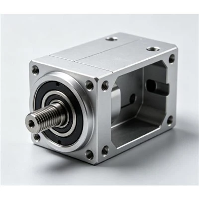
Robotic Joint Flanges are CNC machined components used for mechanical connection, positioning, and support within robotic joint assemblies.
They are produced according to engineering drawings, 3D CAD models, or sample parts. Common machining features include mounting holes, locating bores, threaded interfaces, bearing seats, and reference surfaces.
Aluminum alloys such as 6061, 6063, and 7075 are commonly selected for robotic flange components due to their machinability, structural performance, and weight advantages. Manufacturing processes include CNC milling, drilling, tapping, boring, and surface finishing based on part requirements.
Product Design and Structural Features
Mounting Interface
Robotic joint flanges provide connection points between motors, reducers, bearings, and structural assemblies. Accurate hole patterns and reference surfaces help maintain proper installation alignment.
Positioning Structure
Locating bores, stepped surfaces, and precision machined interfaces support repeatable assembly between connected robotic components.
Weight Optimization
Aluminum alloy construction helps reduce moving component weight while maintaining suitable mechanical strength for robotic applications.
Material Selection and Surface Options
Aluminum Alloy Selection
Material selection depends on mechanical requirements, machining conditions, and weight considerations.
|
Material |
Tensile Strength |
Typical Application |
|
Aluminum 6061 |
260-310 MPa |
General robotic joint structures |
|
Aluminum 6063 |
180-250 MPa |
Lightweight mounting components |
|
Aluminum 7075 |
450-540 MPa |
Higher strength connection parts |
Surface Treatment Options
|
Treatment |
Purpose |
|
Anodizing |
Corrosion protection and surface finishing |
|
Hard Anodizing |
Increased surface hardness and wear resistance |
|
Powder Coating |
Protective surface layer |
|
Electrophoresis |
Uniform surface protection |
CNC Machining Capabilities
Multi-Axis Machining
Complex robotic joint flange geometries can be processed through multi-axis and multi-side machining operations. This helps maintain accurate relationships between mounting holes, locating surfaces, bores, and other functional areas during production.
Precision Feature Machining
Typical machining operations include:
● CNC milling for structural profiles, pockets, and mounting surfaces
● Drilling and tapping for threaded holes and assembly connections
● Boring and counterboring for accurate bore dimensions and component alignment
● Pocket machining for weight reduction and integrated structural features
Drawing-Based Production
Manufacturing is carried out according to approved drawings, 3D CAD models, dimensional specifications, tolerance requirements, and surface finishing instructions. Production processes are controlled to ensure each component meets the defined assembly and functional requirements.
Technical Specifications
|
Parameter |
Specification |
|
Material Options |
Aluminum 6061 / 6063 / 7075 |
|
Machining Process |
CNC milling, drilling, tapping, boring |
|
Typical Tolerance |
±0.01 mm to ±0.05 mm |
|
Surface Finish |
Anodizing, hard anodizing, coating, painting |
|
Part Size |
Custom according to drawing requirements |
|
Production Type |
Prototype, small batch, repeat production |
|
Inspection Method |
Dimensional measurement, visual inspection, process verification |
|
Manufacturing Input |
2D drawings, 3D CAD models, sample parts |
Applications and Industry Use
Industrial Robotics
Used in robotic joint structures requiring accurate mechanical connection between moving components.
Automation Equipment
Applied in automated systems where customized mounting dimensions and lightweight structures are required.
Precision Motion Systems
Suitable for assemblies where positioning accuracy and mechanical alignment affect system performance.
Robotic Development Projects
Used for customized robotic structures requiring specific flange dimensions, interfaces, and mounting configurations.
Quality Control and Manufacturing Verification
Material Verification
Incoming materials are checked according to specified alloy requirements before machining begins.
Dimensional Inspection
Critical dimensions including bore diameter, hole position, thickness, and surface flatness are inspected according to engineering requirements.
Process Documentation
Production records and inspection data support repeat manufacturing and dimensional consistency between production batches.
Customization and Supplier Support
Drawing Review
Manufacturing requirements are reviewed according to part drawings, CAD models, material specifications, and finishing requirements.
Process Planning
Machining methods are evaluated based on component structure, tolerance requirements, and production quantity.
Production Support
Manufacturing support covers prototype development, production validation, and recurring component supply.
Procurement Considerations
Define Part Requirements
Purchasers should confirm flange dimensions, mounting interfaces, tolerance requirements, material specifications, and surface treatment needs.
Review Manufacturing Capability
Important evaluation factors include machining processes, inspection methods, engineering communication, and production consistency.
Prepare Technical Information
Complete drawings, 3D models, quantity requirements, and quality specifications help improve quotation accuracy and production planning.
FAQ
Q: What materials are commonly used for robotic joint flanges?
A: Aluminum 6061, 6063, and 7075 are commonly used depending on structural requirements, weight considerations, and machining conditions.
Q: Can robotic joint flanges be manufactured from customer drawings?
A: Yes. Parts can be produced according to 2D drawings, 3D CAD models, or approved sample components.
Q: What machining features can be produced on robotic flanges?
A: Common features include mounting holes, threaded holes, precision bores, locating surfaces, bearing seats, and connection interfaces.
Q: What tolerance range can be achieved?
A: Typical CNC machining tolerance ranges from ±0.01 mm to ±0.05 mm depending on part geometry and functional requirements.
Q: Are surface treatments available for robotic flange components?
A: Yes. Surface treatments include anodizing, hard anodizing, powder coating, electrophoresis, and other finishing processes based on application requirements.
Hot Tags: robotic joint flanges, China robotic joint flanges manufacturers, suppliers, factory, 5 axle cnc, axis cnc, cnc, cnc services, cnc metal turning, cnc stainless steel machining
You Might Also Like




Send Inquiry