


Pneumatic Control Manifolds
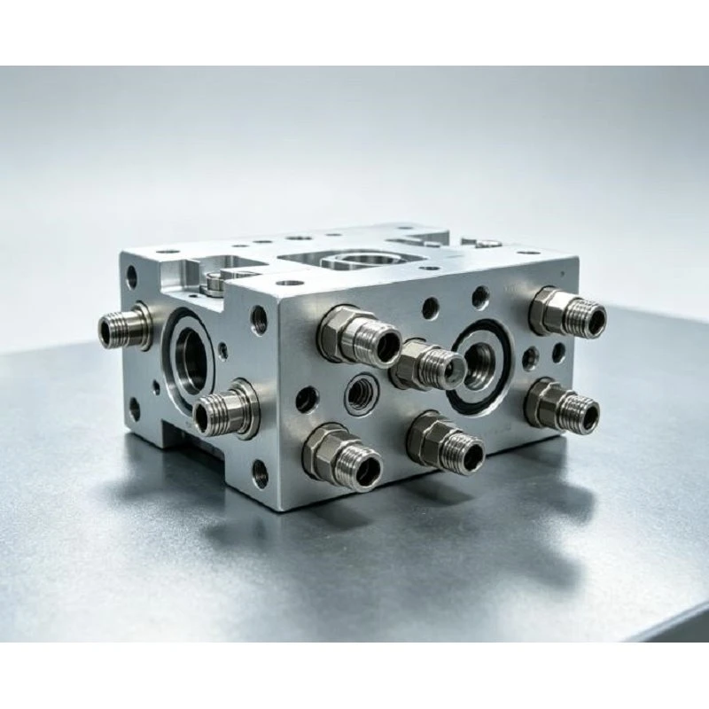
Pneumatic control manifolds combine air ports, internal passages, threaded connections, mounting features, and sealing surfaces in one CNC-machined block. The manifold routes compressed air between valves, actuators, cylinders, and pneumatic circuits while keeping connection points within a defined assembly.
The block geometry is determined by port position, passage routing, mounting dimensions, thread specification, material, and sealing requirements. Production follows approved 2D drawings, 3D CAD models, samples, or defined technical specifications.
Manifold Configurations
Port Layout
Port quantity, position, orientation, thread size, and depth are specified according to the pneumatic circuit. Ports can be arranged across multiple faces when the equipment requires different connection directions.
Internal Passages
Internal passages connect designated ports through the manifold body. Passage diameter, drilling depth, intersection position, and sealing locations are controlled from the approved drawing.
Mounting Features
Mounting holes, counterbores, locating features, and reference surfaces can be integrated into the block. Their position is coordinated with the port layout and equipment interface.
Material Selection
Aluminum Alloys
6061 aluminum is suited to manifold bodies where low weight and machinability are important. 7075 aluminum is used when higher material strength is required.
Stainless Steel
Stainless steel is suitable for assemblies requiring greater corrosion resistance and material durability.
Brass
Brass provides good machinability and is suitable for manifold bodies with threaded connection features and moderate structural requirements.
Material grade and condition should be defined on the drawing or purchase specification before production.
Key Specifications
|
Parameter |
Typical Specification |
|
Product Type |
CNC Machined Pneumatic Control Manifold |
|
Materials |
Aluminum, Stainless Steel, Brass |
|
Aluminum Grades |
6061-T6, 7075-T6 |
|
Dimensional Tolerance |
±0.01 to ±0.05 mm, according to feature requirements |
|
Port Quantity |
2 to 20+ |
|
Thread Size |
M3 to M24 or equivalent |
|
Internal Passage Diameter |
2 to 20 mm |
|
CNC Machining |
3-axis, 4-axis, 5-axis |
|
Surface Treatment |
Anodizing, hard anodizing, sandblasting, or specified finish |
|
Inspection |
Dimensional, thread, visual, and drawing-based inspection |
Manufacturing Process
Drawing Review
The released drawing or CAD model is checked for material, critical dimensions, port locations, passage geometry, thread details, sealing features, and machining access before the process route is established.
CNC Machining
Milling forms the external profile, mounting surfaces, pockets, and reference features. Drilling and tapping produce connection ports, while cross-drilling creates interconnected internal passages.
Deburring and Cleaning
Machined edges, ports, and passage openings are deburred after machining. Internal passages and connection areas are cleaned before inspection or surface treatment.
Surface Treatment
The specified finish is applied according to material and dimensional requirements. Masking areas are identified where coating or anodizing could affect critical interfaces.
Critical Quality Points
Passage Geometry
Passage diameter, drilling depth, and intersection position determine how air moves between designated ports. These features are checked against the released manifold drawing.
Thread Accuracy
Port threads require the specified size, depth, form, and orientation. Thread features are inspected according to the drawing and connection requirements.
Sealing Surfaces
O-ring grooves, sealing faces, and port sealing areas require controlled dimensions and surface condition. These features are inspected according to their specified tolerances.
Mounting Alignment
Mounting holes, locating features, and reference faces determine the manifold position within the equipment. Hole locations and datum relationships are checked against the defined assembly dimensions.
Applications
Pneumatic Automation
Used for centralized air distribution in automated equipment containing valves, cylinders, actuators, and pneumatic control circuits.
Machine Control
Suitable for machine assemblies where multiple pneumatic connections need to occupy a defined mounting area.
Actuator Systems
Multiple air connections can be grouped around pneumatic actuators to organize circuit routing within the equipment.
Custom Equipment
Custom manifold blocks are used where port arrangement, mounting pattern, passage routing, or overall dimensions must match dedicated equipment.
Inspection and Documentation
Dimensional Inspection
Inspection covers overall dimensions, mounting locations, port positions, thread features, sealing surfaces, and other drawing-controlled characteristics.
Material Verification
Material grade and specified condition are checked against the production requirements. Material information can be recorded with the corresponding production documentation.
Inspection Records
Drawing revision, material specification, dimensional results, surface treatment requirements, and defined inspection criteria can be maintained with the production record.
Customization and Supply
Prototype Production
Prototype machining provides a practical stage for checking manifold dimensions, port positions, mounting interfaces, and passage requirements before repeat production.
Drawing-Based Production
The production package can include 2D drawings, 3D CAD data, material grade, thread specifications, surface treatment, dimensional tolerances, and inspection requirements.
Repeat Production
The approved drawing revision and production specification provide the reference for subsequent orders. This keeps the manifold configuration aligned with the released design.
Request a Pneumatic Manifold Quote
For quotation, provide the 2D drawing or 3D CAD model together with material grade, quantity, port and thread specifications, surface treatment, critical tolerances, and inspection requirements.
For manifolds with interconnected passages, the drawing should identify passage diameters, drilling depths, sealing locations, and critical features. This information allows the machining route and inspection points to be reviewed before production.
FAQ
Q: What materials are used for pneumatic control manifolds?
A: Common material options include 6061-T6 and 7075-T6 aluminum, stainless steel, and brass. Selection depends on weight, strength, corrosion conditions, machining requirements, and the operating environment.
Q: Can the internal pneumatic passages be customized?
A: Yes. Passage diameter, drilling depth, routing, and intersection locations are defined according to the pneumatic circuit and manifold drawing. Cross-drilling is used where internal connections require access from different faces.
Q: Can port locations and thread sizes be customized?
A: Yes. Port quantity, position, orientation, thread size, and depth are specified according to the equipment interface and pneumatic circuit.
Q: What information is needed for quotation?
A: A 2D drawing or 3D CAD model should be provided with material, quantity, port and thread details, surface treatment, critical tolerances, and required inspection or testing information.
Q: Can the same manifold be supplied for repeat production?
A: Yes. The approved drawing revision, material specification, machining requirements, surface treatment, and inspection criteria can serve as the production reference for subsequent orders.
Hot Tags: pneumatic control manifolds, China pneumatic control manifolds manufacturers, suppliers, factory, axis of cnc, cnc machining metal, high precision cnc machining, high precision machining, precision cnc machining, precision machining service
Previous
Hydraulic Distribution ManifoldsYou Might Also Like


Send Inquiry